Saluti a tutti.
Torno su questo forum dopo parecchio tempo, parte del quale passato a realizzare con successo alcuni strumenti per la registrazione dei raggi cosmici (muoni).
Gli strumenti che ho costruito impiegano come sensori tubi Geiger arrivati dall’Ucraina e dalla Russia.
Qualcuno di questi tubi, in particolare gli SBM19, hanno il tubo vero e proprio malamente crimpato sui due tappi isolanti. La conseguenza è che, applicando solo un leggero movimento di torsione sui tappi, essi ruotano un po', facendo così presumere che la tenuta stagna sia persa ed il gas interno abbia avuto modo di uscire. Tuttavia essi funzionano, il che fa pensare che tutto sommato non si tratti di una costruzione particolarmente critica.
Basandomi su questa idea nonché sul sezionamento ed ispezione di uno di questi tubi che era particolarmente malandato, ho constatato la semplicità (apparente!) della costruzione, ed ho pensato che potevo provare a costruirmene qualcuno in casa.
Per il primo tentativo ho usato un tubo di plastica, all’interno del quale ho collocato un ritaglio di un foglio di acciaio Ixox dello spessore di 0,02 mm. Data la sua leggerezza, simile a quella della carta, esso ha aderito perfettamente alla parete interna del tubo coprendone tutta la superficie e formando così il catodo metallico. L’anodo è costituito da un filo di NiCr da 0,2 mm. di diametro, ben teso al centro del tubo e tenuto il posizione da due tappi isolanti. Completa il sensore una miscela di gas Argon e propano immessa nel tubo sigillato.
Dato che il pseudo Geiger non funzionava, ho fatto molte altre prove cambiano dimensioni del tubo e percentuali della miscela dei due gas. Ho anche variato la pressione da quella atmosferica fino ad abbassarla a 10 mm. di mercurio, ed ho cambiato anche il voltaggio dell’alimentazione in un range da 500 a 4000V. Il tutto provando varie combinazioni fra questi fattori.
Non riscontrando risultati positivi, sono passato ad una diversa geometria, costruendo una cella piana così formata: due PCB con le parti ramate che si affacciano parallelamente a distanza di 5 mm, e a metà di questo gap ho collocato quattro fili metallici anch'essi paralleli alle schede pcb ed equamente spaziati. Il tutto ben isolato e chiuso in modo da formare una camera stagna in cui ho immesso il gas. Risultato? Il medesimo dei tubi, cioè nullo, nonostante la possibilità di cambiare, oltre alle cose già dette, anche la distribuzione dell’alimentazione: una scheda al positivo e l’altra al negativo, oppure ambedue al negativo e i fili al positivo.
Sull’oscilloscopio si vedono sì le tracce di certi segnali, ma la loro frequenza non cambia se si avvicina una sorgente radioattiva, il che significa che il sensore è totalmente sordo alle particelle alfa e beta, e forse anche ai fotoni gamma. Esattamente come i primi tubi geiger da me costruiti. Resta da capire i segnali che si vedono da cosa sono generati. Muoni? Troppo bello per essere vero. Infatti, anche disponendo il sensore in modo che catturi le radiazioni solo in orizzontale, la frequenza dei segnali rimane la stessa, mentre in questo caso dovrebbe ridursi quasi a zero.
Morale della favola: so che questo forum è frequentato da molti esperti in materia. Uno di questi mi aiuta molto nei miei tentativi, e di questo gli sono grato. Tuttavia non voglio abusare della sua pazienza. Spero inoltre che qualcun altro dei frequentatori si sia già cimentato nella costruzione di un sensore Geiger e voglia condividere le sue esperienze, oppure sappia darmi comunque qualsiasi consiglio/idea in proposito. Non sono un esperto nel campo delle particelle, né conosco a fondo l’elettronica. Tuttavia, grazie ai consigli e alle varie ricerche che ho fatto, me la cavo. Mi aiuta molto anche la curiosità e la caparbietà con cui cerco di risolvere i problemi.
Nella speranza che qualcuno risponda, saluto tutti.
Antonio Zanardo
Autocostruzione sensore Geiger?
Re: Autocostruzione sensore Geiger?
Ho trovato questo magari può esserti utile:
[External Link Removed for Guests]" onclick="window.open(this.href);return false;
[External Link Removed for Guests]" onclick="window.open(this.href);return false;
-
marconmeteo
- Moderatore
- Messaggi: 4392
- Iscritto il: 08/10/2015, 21:20
- Località: Marcon (VE)
- Contatta:
Re: Autocostruzione sensore Geiger?
Grazie cicastol per il documento, molto interessante. Pensavo che un motivo di scarsa sensibilità possa essere dovuto che in entrambi i casi, oltre al fine lamierino metallico che fa da catodo (il foglietto d'acciaio nel primo esperimento e lo strato di rame del pcb, nel secondo), cè anche del materiale (tubetto di plastica e fibra di vetro dei pcb) che ostacola il passaggio delle particelle; i tubi geiger sono costruiti con metallo quanto più fine possibile proprio per ostacolare il meno possibile il passaggio delle radiazioni.
[External Link Removed for Guests]
"Due cose sono infinite: l'universo e la stupidità umana, ma riguardo all'universo ho ancora dei dubbi" - Albert Einstein
IU3ARP
"Due cose sono infinite: l'universo e la stupidità umana, ma riguardo all'universo ho ancora dei dubbi" - Albert Einstein
IU3ARP
-
antonio zanardo
- Messaggi: 40
- Iscritto il: 27/06/2017, 23:28
Re: Autocostruzione sensore Geiger?
Ringrazio cicastol e marconmeteo per le rapide risposte.
il pdf segnalato da Cicastol è interessante in quanto fornisce qualche formula per il dimensionamento dei vari organi dei tubi Geiger. Da una prima lettura risulta che il filo anodico dovrebbe essere il più sottile possibile, dell'ordine di 80-100 micron, ma quello del tubo russo CTC6, equivalente all'SBM19, ha il diametro di 0.5mm, ossia 5 volte rispetto ai calcoli. Preciso però che devo ancora leggermi meglio tutto l'articolo.
A marconmeteo rispondo che non so quale effetto abbia la plastica sulle particelle alfa e beta o sui raggi gamma di bassa energia. Quasi sicuramente blocca le particelle alfa, molto probabilmente le beta, e per i fotoni gamma dipende dalla loro energia. Forse sono proprio i gamma sufficientemente energetici a produrre i segnali rivelati dall'oscilloscopio, ma come accertarsene?
I muoni, che sono le particelle che interessano a me, possono attraversare decine di metri di materia o un metro di Fe prima di attenuarsi in modo apprezzabile, per cui non hanno sicuramente problemi a passare spessori di qualche millimetro di qualsiasi materiale.
Tuttavia mi verrebbe da escludere proprio i muoni in quanto essi "piovono" verticalmente dal cielo, per cui disponendo il sensore autocostruito in modo che riveli solo la radiazione orizzontale, dovrei notare una forte riduzione dei conteggi. Questo infatti accade con gli altri strumenti che ho costruito e che impiegano Geiger commerciali, ma non con i sensori che ho costruito io.
Restano quindi i gamma, ma saranno proprio loro? A questo proposito chiedo: quali radiazioni produce la pechblenda?
E con questo interrogativo me ne vado a letto.
Antonio Zanardo
-
antonio zanardo
- Messaggi: 40
- Iscritto il: 27/06/2017, 23:28
Re: Autocostruzione sensore Geiger?
Ulteriori sviluppi.
Per sciogliere i legittimi dubbi di marconmeteo circa la "trasparenza" alla radiazione del tubo di plastica e della lamina di acciaio inox usati nelle mie prove, ho fatto il seguente test che è servito anche a chiarire un fatto importante.
Ho costruito con il materiale in mio possesso un nuovo tubo di dimensioni identiche ad un piccolo tubo Geiger commerciale in mio possesso. Riempitolo di Argon puro, e constatato che il Geiger commerciale funzionava, mentre * il mio NO * , sono andato per esclusione facendo le seguenti prove allo scopo di individuare la causa del mancato funzionamento,.
1) ho collegato il tubo Geiger commerciale all' alimentazione ed all'oscilloscopio, e, messo a contatto con la sorgente radioattiva, ne ho rilevato i conteggi.
2) ho poi infilato il Geiger in un tubo di plastica utilizzato per i geiger autocostruiti. I conteggi non hanno subito apprezzabili variazioni.
3) infine ho ricoperto il Geiger+tubo di plastica con un foglio di Inox da 2 centesimi di spessore, identico a quello usato nelle mie prove. I conteggi hanno subìto solo un leggerissimo calo.
La prova taglia la testa al toro: il responsabile del mancato funzionamento dei miei prototipi non può essere né la plastica né la lamina di inox. Rimane solo il gas.
Nelle mie prove ho variato anche la pressione del gas fino a portarla a circa 1/10 di atmosfera, ma senza risultato. Evidentemente l'Argon non è il più adatto per questo tipo di impiego.
Ora c'è il problema di trovare altri gas per fare ulteriori prove. Non sarà facile, ma spero di essere vicino alla soluzione.
Antonio Zanardo
-
marconmeteo
- Moderatore
- Messaggi: 4392
- Iscritto il: 08/10/2015, 21:20
- Località: Marcon (VE)
- Contatta:
Re: Autocostruzione sensore Geiger?
Leggendo su wikipedia relativamente ai gas utilizzati nei tubi GM
parlano di una miscela denominata Penning mixture, dal nome dello scopritore [External Link Removed for Guests]" onclick="window.open(this.href);return false;
Spero possa essere di aiuto....
Ho trovato anche questo: [External Link Removed for Guests]" onclick="window.open(this.href);return false;
parlano di una miscela denominata Penning mixture, dal nome dello scopritore [External Link Removed for Guests]" onclick="window.open(this.href);return false;
Spero possa essere di aiuto....
Ho trovato anche questo: [External Link Removed for Guests]" onclick="window.open(this.href);return false;
[External Link Removed for Guests]
"Due cose sono infinite: l'universo e la stupidità umana, ma riguardo all'universo ho ancora dei dubbi" - Albert Einstein
IU3ARP
"Due cose sono infinite: l'universo e la stupidità umana, ma riguardo all'universo ho ancora dei dubbi" - Albert Einstein
IU3ARP
Re: Autocostruzione sensore Geiger?
Magari può aiutare (brevi estratti da alcune pubblicazioni). In caso interessasse, posso cercare in altri libri...
Measurement and detection of radiation / Nicholas Tsoulfanidis ha scritto: [...]As discussed in Sec. 5.6.1, the quenching gas in a GM counter is either an organic polyatomic molecule such as ethyl alcohol, or a halogen such as bromine or chlorine. A typical mixture is 0.1 percent chlorine in neon. The gas pressure in a GM counter is, in most cases, less than 1 atm. The pressure affects the operating voltage.[...]
Handbook of Radioactivity Analysis, Second Edition / Michael F. L’Annunziata ha scritto: A. Designs and Properties of Geiger-Mueller Counters
1. Fill Gas
The fill gas for Geiger-Mueller counting tubes has to meet requirements similar to those for the fill gas for proportional counters. Argon and helium are most frequently used. The gas pressure is on the order of tenths of bars, and depending on the size and shape of the tubes a voltage on the order of hundreds of volts is applied. Geiger-Mueller tubes are usually permanently sealed and operate at low gas pressure, although designs have been realized using atmospheric pressure and flow-through to replenish the fill gas and flush out impurities.
2. Quenching
After the termination of the discharge, the slowly migrating positive ions of the fill gas finally arrive at the cathode, which is usually the outer wall of the counting tube. At this electrode the cations capture electrons from the cathode surface and a corresponding amount of energy is liberated. If this liberated energy exceeds the ionization energy of the cathode material, additional electrons are set free from this electrode. These newly generated free electrons migrate to the anode and create another avalanche. This finally results in a continuous output of pulses. The probability of this additional electron drift is rather low, but because of the high number of cations at the field strength conditions in a Geiger-Mueller tube, this effect of multiple pulses is observed. With Geiger-Mueller tubes special precautions have to be taken to prevent the formation of additional avalanches. This can be done by reducing the bias voltage after the Geiger discharge. This external quenching can be achieved by using a suitable electronic circuit (resistor and capacitance) that determines the time of restoration of the high voltage following a Geiger discharge. The restoration time is usually on the order of milliseconds and therefore this design is suitable only for low count rates.
It is more common today to use internal quenching, which involves the addition of a suitable compound to the fill gas. The ionization energy for this additive to the fill gas (quench gas) must be lower than the ionization energy for the fill gas. Although confusing, the same expression ‘‘quench gas’’ is used for both the additive to a fill gas of proportional counters, which has to absorb UV photons, and the additive to a fill gas in the Geiger-Mueller tube, which should be able to neutralize the drifting ions of the original filling gas by electron transfer. The ions of the quench gas migrate to the cathode and are also neutralized. But the liberated ionization energy is now consumed by the quench gas and causes dissociation of the quench gas molecules. Some quench gases, such as halogens (e.g., chlorine or bromine), show spontaneous recombination; other quench gases, such as organic compounds (e.g., ethanol), are consumed, and therefore the lifetime of an organic-quenched Geiger-Mueller tube is limited to about 109 counts. Quench gases are usually added at an amount of several percent to the fill gas of the Geiger-Mueller tube. A relatively long time is needed (100–500us) to clean the positive ions that are formed during the avalanche propagation.
The transition from proportional mode to Geiger-Mueller mode takes place at increasing field strength. Golovatyuk and Grancagnolo (1999) could demonstrate that this transition also depends on the concentration of a quenching gas. This fact may be of relevance if pulse shape analysis is used for particle identification. If the concentration of quenching gas is low, gas amplification, as a function of high voltage, increases more rapidly and the boundary between the proportional region and the Geiger-Mueller region may be crossed easily. Results of pulse shape analysis may not be interpreted correctly.
Radiation Detection and Measurement / Knoll, 4th ed. ha scritto:[...]It is much more common to prevent the possibility of multiple pulsing through internal quenching, which is accomplished by adding a second component called the quench gas to the primary fill gas. It is chosen to have a lower ionization potential and a more complex molecular structure than the primary gas component and is present with a typical concentration of 5-10%. Although it is given the same name as the component added to proportional counter gases to absorb UV photons, the quench gas in a Geiger counter serves a different function. It prevents multiple pulsing through the mechanism of charge transfer collisions. The positive ions formed by the incident radiation are mostly of the primary component, and they subsequently make many collisions with neutral gas molecules as they drift toward the cathode. Some of these collisions will be with molecules of the quench gas and, because of the difference in ionization energies, there will be a tendency to transfer the positive charge to the quench gas molecule. The original positive ion is thus neutralized by transfer of an electron and a positive ion of the quench gas begins to drift in its place. If the concentration of the quench gas is sufficiently high, these charge-transfer collisions ensure that all the ions that eventually arrive at the cathode will be those of the quench gas. When they are neutralized, the excess energy may now go into disassociation of the more complex molecules in preference to liberating a free electron from the cathode surface.
With the proper choice of quench gas, the probability of disassociation can be made much larger than that of electron emission, and therefore no additional avalanches are formed within the tube.
Many organic molecules possess the proper characteristics to serve as a quench gas. Of these, ethyl alcohol and ethyl formate have proved to be the most popular and are widely used in many commercial G-M tubes. Because the quench gas is disassociated in carrying out its function, it is gradually consumed during the lifetime of the tube. An organic quenched tube may typically have a limit of about 109 counts in its useful lifetime before multiple pulsing can
no longer be prevented because of depletion of the quench gas.
To avoid the problem of limited lifetime, some tubes use halogens (chlorine or bromine) as the quench gas. Although the halogen molecules also disassociate when carrying out their quenching function, they may be replenished by spontaneous recombination at a later time. In principle, halogen-quenched tubes therefore have an infinite lifetime and are preferred in situations where the application involves extended use at high counting rates. However, there are other mechanisms besides the consumption of the quench gas that limit the lifetime of Geiger tubes. Two of the more important appear to be contamination of the gas by reaction products produced in the discharge and changes on the anode surface caused by the deposition of polymerized reaction products.[...]
Questo è più dedicato ai rilevatori proporzionali...Detection and Measurement of Nuclear Radiation / G.D. O'Kelley ha scritto:[...]If a positively charged rare-gas ion strikes the cathode, a secondary electron may be produced. This additional electron will result in another discharge unless provision is made to prevent multiple discharges by quenching. Almost all modern Geiger tubes are self -quenching; that is, they contain some polyatomic gas which brings a halt to the process when the positive-ion sheath reaches the cathode. Argon-filled Geiger tubes frequently use alcohol as the quenching gas; in such a tube, an argon ion makes frequent collisions with argon atoms and alcohol molecules on its way to the cathode. The probability is very high that an argon ion will be neutralized in an encounter with an alcohol molecule, but the opposite transfer of charge is not energetically possible. Therefore, the positive-ion sheath which finally reaches the cathode is composed only of alcohol molecular ions.
These ions cannot release secondary electrons; instead, they become neutralized at the cathode surface and dissociate harmlessly. The organic gas eventually becomes depleted after about 109 counts have occurred, and the counter is no longer usable.
The consumption of quenching gas increases with operating voltage. The life of Geiger counters has been extended greatly through the use of halogens as quenching gases. A common filling is about 0.1% chlorine in neon. The quenching mechanism is the same as just described for organics, except that after the diatomic chlorine molecules dissociate at the cathode, they eventually recombine; thus, the quenching gas is continually replenished. This makes it possible to operate the tube at very high voltages without harm, and so very large signal pulses are obtainable.[...]
Experimental Techniques in Nuclear and Particle Physics / Stefaan Tavernier ha scritto:[...]Gas mixtures: The gas mixture used in a proportional tube is very important. The gas should not contain any electronegative component. An electronegative molecule tends to form negative ions by capturing the electrons. The result is that the positive and the negative charge carriers are both ions and gas multiplication will only begin at much larger voltages. Moreover, as soon as there is charge amplification, both the positive and the negative ions give rise to multiplication resulting in an avalanche that never stops growing, ending in a discharge. Since oxygen is electronegative, air is not a good working gas for proportional tubes.
An obvious choice for the gas filling of a proportional tube is a noble gas. A noble gas certainly is not electronegative; moreover noble gases can easily be purified avoiding impurities that give rise to complications. Finally, a noble gas has the advantage that the collisions of the electrons with the gas atoms are elastic below the ionisation threshold. Since noble gas molecules are single atoms, there are no rotation or vibration states that can absorb the electron energy during the collisions.
As a result, avalanche multiplication occurs at a lower voltage in a noble gas than in other gases. Of all the noble gases, argon is the least expensive, therefore nearly all proportional tubes use a gas filling based on argon. However, with pure argon the gain of a proportional tube is limited to a few times 100. This is due to the following mechanisms. The ionisation potential of argon is 11.6 eV, while the ionisation potential of all metals is less than 11.6 eV. The ionisation potential of copper, for example, is 7.7 eV. Therefore, electron–ion recombination, or exited argon atoms, will give rise to VUV photons that will be able to extract electrons from the cathode. If the average number of such secondary electrons is larger than one, each avalanche will, on average, give rise to more than one new avalanche. The number of avalanches will grow exponentially until the tube is filled throughout with avalanches, and the voltage drops to a very low value due to the large current drawn by all these avalanches.
Another reason why pure argon is not suitable as a fill gas is the fact that the argon ions arriving at the cathode will form neutral argon atoms by extracting an electron from this cathode and can dissipate the energy liberated in doing so by extracting an additional electron from the cathode. Again, if for one avalanche the average number of electrons extracted from the cathode is larger than one, the number of avalanches keeps increasing until breakdown occurs.
To prevent these phenomena from occurring, a small amount (typically 10%) of a polyatomic gas is added. This is called a quenching gas and several polyatomic gases can be used for this purpose. Isobutane (C4H10) or methane (CH4) is often used as quenching gas. Since these polyatomic gases have many rotation and vibration degrees of freedom, they will readily absorb these UV photons without being ionised. Moreover, in the collisions between the argon ions and quenching gas molecules, the charge will be transferred from the argon atom to the quenching gas molecule because the binding energy of the electron is lower in the quenching gas. When the charged quenching gas molecule arrives at the cathode, the likelihood of extracting an electron is much smaller, because this molecule has many other ways of dissipating the extra energy. In a gas mixture consisting of argon and ≈10% of a suitable quenching gas, stable operation with electron multiplication of 106 is possible.
The choice of gas mixture is very important if the detector has to work at a high count rate for a long time. The avalanche produces a large number of excited molecules and in this way initiates complex chemical reactions. In particular, the quenching gas, usually a gas containing carbon, participates in the formation of more complex molecules. These complex molecules are deposited on the electrodes in the proportional tube and, in particular, on the anode. This forms a thin insulating layer on the surface of anode wires, and this prevents the normal operation of the proportional tube. Finding a gas mixture that minimises these problems is largely done empirically. It is found that not only the gas mixture, but also all other materials used in the construction of the detector have a very strong influence on the ageing effect. Trace amounts of impurities in the gas or in other construction materials can have a dramatic effect on the ageing properties of a wire chamber.
With correct choice of materials and proper care, it is found that a wire chamber can cope with a total accumulated charge of more than 1 coulomb/cm of anode wire. This means that with a gas gain of 104, and a rate of 104/s minimum ionising tracks per mm of anode wire, the chamber will work for 10 years without problems.
Figure 4.13 shows the signal amplitude in a proportional tube as a function of the externally applied voltage. In this plot, it was assumed that the primary charged particles produce 100 electron–ion pairs in the gas. The following operational regimes
of the chamber can be distinguished.
Ionisation chamber: at a voltage of a few 100 V, the device works as an ionisation chamber. All the charges are collected but there is no charge amplification. The amplitude of the pulse is therefore only 100 electron charges. Proportional regime: As the voltage is increased, charge multiplication sets in.
The charge amplification increases more or less exponentially with the voltage. As long as the gain is less than about 105, each electron arriving at the anode receives the same amplification, regardless of how many electrons there are in total. In this case, the amplitude of the output pulse is proportional to the amount of primary ionisation in the gas. The names ‘proportional regime’ and ‘proportional counter’ refer to this property of the counter.
Non-proportional regime: As the voltage is increased further, the gain becomes very large and the proportionality property no longer holds. This is because the first electrons arriving at the anode undergo a very large amplification. After the electrons from this first avalanche have reached the anode, they leave behind a large number of positive ions that drift slowly towards the cathode. These positive ions will weaken the field close to the anode wire. Therefore, the electrons arriving later see a smaller field and are amplified less than the first electron.
The Geiger regime: If the voltage is increased further, at some point the Geiger regime is reached. A stable Geiger regime is only reached for suitable gas mixtures. In this regime, the avalanche extends laterally along the anode wire and eventually fills the whole tube. The extension of the avalanche is due to UV photons formed in the process of avalanche multiplication. These UV photons will ionise molecules some distance away from the original avalanche, inducing further avalanches. Eventually, the anode wire is surrounded along its full length with avalanches.
The avalanche formation stops because the space charge of all these positive ions left behind reduces the electric field close to the wire to a point where there is no more avalanche formation. The voltage drop over the external resistor in series with the voltage power supply also contributes to stopping the avalanche multiplication process.
In the Geiger regime, the pulses are very large and can be several volts. The drawback is that the counter has a very large dead time because one must wait until all the positive ions have been evacuated, and this typically needs several 100 μs. In the proportional regime, the number of charges in each avalanche is much smaller and a new event at the same point is possible before all the charges have been evacuated. Moreover, the avalanche is localised at one point along the wire. The rest of the length of the wire is not affected at all and is ready to accept new events. The count rate achievable in proportional tubes is therefore about 107 pulses per meter of wire, several orders of magnitude larger than what can be achieved with a Geiger counter.[...]
Particle detectors / Grupen & Schwartz ha scritto:[...]A more generally accepted method of quenching in Geiger counters is the method of self-quenching. In self-quenching counters a quench gas is admixed to the counting gas which is in most cases a noble gas.
Hydrocarbons like methane (CH4), ethane (C2H6), isobutane (iC4H10), alcohols like ethyl alcohol (C2H5OH) or methylal (CH2(OCH3)2), or halides like ethyl bromide are suitable as quenchers. These additions will absorb photons in the ultraviolet range (wavelength 100–200 nm) thereby reducing their range to a few wire radii (≈ 100 μm). The transverse propagation of the discharge proceeds only along and in the vicinity of the anode wire because of the short range of the photons. The photons have no chance to liberate electrons from the cathode by the photoelectric effect because they will be absorbed before they can reach the cathode.
After a flux tube of positive ions has been formed along the anode wire, the external field is reduced by this space charge by such an amount that the avalanche development comes to an end. The positive ions drifting in the direction of the cathode will collide on their way with quench-gas molecules, thereby becoming neutralised,
Ar+ +CH4 → Ar + CH+4 . (5.45)
The molecule ions, however, have insufficient energy to liberate electrons from the cathode upon impact. Consequently, the discharge stops by itself.
The charging resistor, therefore, can be chosen to be smaller, with the result that time constants on the order of 1 μs are possible.
Contrary to the proportional mode, the discharge propagates along the whole anode wire in the Geiger mode. Therefore, it is impossible to record two charged particles in one Geiger tube at the same time. This is only achievable if the lateral propagation of the discharge along the anode wire can be interrupted. This can be accomplished by stretching insulating fibres perpendicular to the anode wire or by placing small droplets of insulating material on the anode wire. In these places the electric field is so strongly modified that the avalanche propagation is stopped. This locally limited Geiger mode allows the simultaneous registration of several particles on one anode wire. However, it has the disadvantage that the regions close to the fibres are inefficient for particle detection. The inefficient zone is typically 5mm wide. The readout of simultaneous particle passages in the limited Geiger range is done via segmented cathodes.[...]
Vedi anche "Physics and Engineering of Radiation Detection" di Syed Naeem Ahmed: troppo lungo da digitalizzare e farne l'OCRPhysics for Radiation Protection / Martin ha scritto:[...]A GM tube usually consists of a fine wire electrode (e.g., tungsten) mounted along the axis of a tube containing a mixture of 90% argon and 10% ethyl alcohol (for quenching) at a fraction of atmospheric pressure.A potential difference of 800–2000 V (nominally 900 V) is applied to make the tube negative with respect to the wire. Because of their mode of operation, they cannot be used to identify the type of radiation being detected nor its energy.[...]
Ultima modifica di eliocor il 21/02/2018, 0:34, modificato 3 volte in totale.
٩(•̮̮̃•̃)۶ - Excusatio non petita, accusatio manifesta
Re: Autocostruzione sensore Geiger?
Credo ti possano interessare anche:
[External Link Removed for Guests]" onclick="window.open(this.href);return false;
[External Link Removed for Guests]" onclick="window.open(this.href);return false;
[External Link Removed for Guests]" onclick="window.open(this.href);return false;
[External Link Removed for Guests]" onclick="window.open(this.href);return false;
٩(•̮̮̃•̃)۶ - Excusatio non petita, accusatio manifesta
-
antonio zanardo
- Messaggi: 40
- Iscritto il: 27/06/2017, 23:28
Re: Autocostruzione sensore Geiger?
Grazie eliocor.
Difficile trovare altrove una mole di informazioni simile sui problemi dei Geiger.
Mi pare di capire che il "trucco" dei geiger sta proprio nella formulazione della miscela gassosa e della sua pressione. Del resto ero arrivato anch'io alla conclusione che se i miei prototipi non funzionano la colpa è proprio del gas.
Qui però sorge un dubbio. In un lotto di tubi SBM19 e CTC6 ricevuti recentemente, qualcuno di questi aveva i tappi isolanti che non erano ben bloccati sul tubo, ed il tubo di conseguenza non era più stagno. Probabilmente il gas di riempimento se n'era già andato. Se ne rimaneva ancora un po', certamente non conservava più la pressione originaria. Ho fatto un giro di scotch fra gli isolatori ed il tubo in modo da bloccare alla meno peggio i tappi che si muovono. Ho quindi provato i tubi uno ad uno, quelli "buoni" ben sigillati e quelli danneggiati e... sorpresa! Funzionano tutti allo stesso modo!
Incredibile, ma vero. Ora, leggendo gli articoli postati, si parla di pressioni variabili a seconda della tipologia del Geiger stesso e della miscela di gas che contiene. "The gas pressure in a GM counter is, in most cases, less than 1 atm." Ma altrove si parla di pressioni dell'ordine di 1/10 di atmosfera ed anche meno. Ma allora, come fa l'SBM19 non più stagno a funzionare?
Evidentemente la casistica delle costruzioni è talmente vasta che c'è posto anche per Geiger che funzionano a pressione atmosferica. Sarà così?
Nel testo si parla molto di quenching gas che ha la funzione di evitare la scarica a valanga, riducendo così il dead time ed allungando la vita del tubo. Io però mi interesso della rivelazione dei muoni, che arrivano con un rateo di 0.01 particelle al secondo per cmq. Poca roba, quindi. Nel mio caso il dead time non è molto critico e se anche il tubo fatto in casa durerà poco, ne farò un altro. Per questo insisto nel volerlo costruire: so bene che il risultato sarà scadente, ma a me basta che funzioni più o meno bene, ma che funzioni, cosa che attualmente non fa.
Ad ogni modo gli aticoli postati aggiungono un bel po' di conoscenza, specie su ciò che mi interessa principalmente, cioè la composizione del gas di riempimento. Per le pressioni ed i voltaggi in gioco... si vedrà!
Grazie ancora.
Antonio Zanardo
Re: Autocostruzione sensore Geiger?
Sei proprio sicuro che non siano più stagni?
Come è più che risaputo, ho ben poca esperienza nel campo dei tubi GM (escluso quelli con finestra in mica) ma dubito che il distacco del contatto/cappellotto implichi il degassamento del tubo.
Se la memoria non mi tradisce, ci dovrebbe ad esempio essere il fratello dell'SBM20 (il quinto a partire dall'alto)
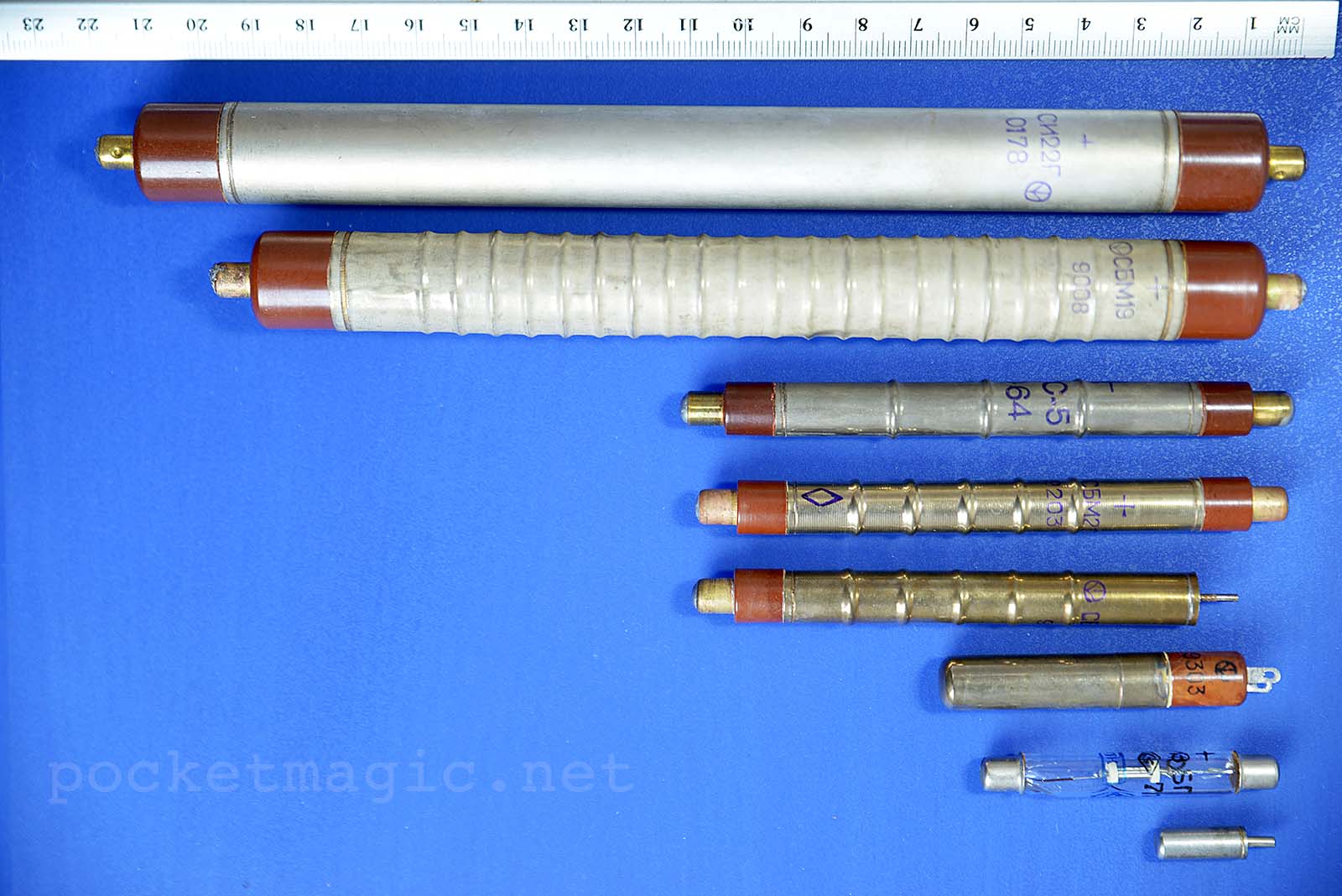
che non ha il cappellotto ma solo il contatto.
Riesci a fare una foto macro ad uno dei contatti/cappellotti distaccati?
Così, solo per curiosità.
Ah, dimenticavo: potresti entrare in maggiori dettagli sulle tue metodologie di costruzione delle sonde?
- metodi per sigillarle
- dove ti procuri le miscele di gas
- come le carichi
- metodi di test delle suddette (cosa usi come alimentatore, strumento per rilevare gli impulsi, ...)
- varie ed eventuali
Come è più che risaputo, ho ben poca esperienza nel campo dei tubi GM (escluso quelli con finestra in mica) ma dubito che il distacco del contatto/cappellotto implichi il degassamento del tubo.
Se la memoria non mi tradisce, ci dovrebbe ad esempio essere il fratello dell'SBM20 (il quinto a partire dall'alto)
che non ha il cappellotto ma solo il contatto.
Riesci a fare una foto macro ad uno dei contatti/cappellotti distaccati?
Così, solo per curiosità.
Ah, dimenticavo: potresti entrare in maggiori dettagli sulle tue metodologie di costruzione delle sonde?
- metodi per sigillarle
- dove ti procuri le miscele di gas
- come le carichi
- metodi di test delle suddette (cosa usi come alimentatore, strumento per rilevare gli impulsi, ...)
- varie ed eventuali
٩(•̮̮̃•̃)۶ - Excusatio non petita, accusatio manifesta
